
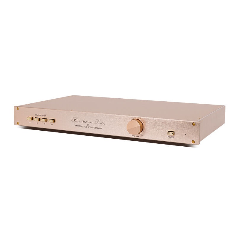
בניית מגבר DIY מסוג A דורשת תשומת לב מדויקת במיוחד לإجراءات הבדיקה והאימות כדי להבטיח ביצועים אופטימליים ואמינות ארוכת טווח. מגברי סוג A מייצגים את שיא נאמנות האודיו, ופועלים עם זרימת זרם רציפה דרך רכיבי הפלט שלהם, מה שדורש בדיקות יציבות מחמירות לאורך תהליך הבנייה. הבנת צעדי הבדיקה החיוניים לאישור היציבות בבניית המגבר שלך מסוג A תאפשר לך להשיג תוצאות ברמה מקצועית, תוך הימנעות ממלכודות נפוצות שעלולות לפגוע בביצועים או לפגוע ברכיבים יקרים.
תהליך אימות היציבות לא mplיפיאר ביתי מדרגה A כולל מספר שלבים של בדיקות, שכל אחד מהם ממוקד על היבטים ספציפיים של התנהגות המעגל בתנאי הפעלה שונים. הבדיקות הללו משתרעות ממדידות ישר בסיסיות ועד לניתוח sophisטי של תגובת התדר, הערכת יציבות תרמית ובדיקת השפעת שינוי עומס. ביצוע תקף של שלבי האימות האלה מבטיח שהmplיפיאר שלכם יספק ביצועים עקביים לאורך טווח ההפעלה המתוכנן שלו, תוך שמירה על איכות השמע העליונה שעושה את טופולוגיית ה- Class A כה רצויה בקרב חובבי שמע ו среди מקצוענים כאחד.
אימות נקודת הפעולה הראשונית בזרם ישר
מדידת זרם ההטיה והתאמתו
הבסיס של כל מגבר ביתי יציב מדרגה A מתחיל במדידת זרם ההטיה המדויקת ובהגבתו. התחל על ידי מדידת זרם השקט דרך כל רכיב פלט באמצעות רב-מודד דיגיטלי מדויק המסוגל למדוד זרמים בטווח של 10–100 מיליאמפר בדיוק גבוה. חבר את הרב-מודד בטור עם כל טרנזיסטור פלט או MOSFET, תוך ודאות שהקוטביות נכונה כדי למנוע נזק לרכיבים רגישים. זרם ההטיה חייב להתאים לנתוני העיצוב בתוך סובלנות של 5–10%, בדרך כלל בטווח של 50 עד 200 מיליאמפר, בהתאם לטופולוגיה הספציפית של המעגל שלך ולבחירת הרכיבים.
תפקידה של הפעולה המטבילה את הטמפרטורה הוא קריטי בהבטחת תנאי קיזוז יציבים במהלך פעולת המגבר הבנוי-בעצם (DIY) במודל A. עקובו אחר זרם הקיזוז בזמן שמעלים בהדרגה את טמפרטורת הסביבה באמצעות מקור חום מבוקר, ובחנו כיצד מגיב מעגל ההגנה מפני חום לשינויי הטמפרטורה. לעיצוב תקין של מעגל מעקב حراري יש לשמור על זרם הקיזוז בתוך טווח של 15–20% מערכו הנומינלי, לאורך טווח טמפרטורות של 25–65 מעלות צלזיוס. אם מתרחשת סטייה מוגזמת, בדקו את הקישור החום בין רכיבי חישוב הטמפרטורה לבין רכיבי הפלט, ודאגו שהריכוז ללוח התפזרות החום מתבצע כראוי וששכבת החומר התרמי הושמה כראוי.
אבחון יציבות מסילות אספקת הכוח
מדודו את יציבות מתח ה-DC בכל מסילות האספקה החשמלית בתנאי אין עומס ובתנאי עומס מלא כדי לאשר את התפקוד הנכון של מערכות הרגולציה ואת היכולת הסUFFICIENT של זרם. השתמשו במVoltמטר דיגיטלי באיכות גבוהה כדי לרשום את מתחי המסילות תוך שימור צפייה בשינויים גדולים במתח או בצ fluctuations שמצביעים על תכנון לקוי של אספקת החשמל או על דעיכה של רכיבים. מתחי המסילות החיובית והשלילית חייבים להישאר מאוזנים בתוך טווח של 1–2% בכל תנאי פעולות, מה שמבטיח פעולה סימטרית של מעגל המגבר ה-"Class A" שתוכלו לבנות בעצמכם.
מדידת מתח הגלגול על מסילות האספקה מספקת תובנות קריטיות לגבי יעילות הסינון ומקורות פוטנציאליים של עיוות בתדר נמוך. חברו אוסצילוסקופ על כל מסילת מתח באמצעות מחוללי מתח מתאימים, אם יש צורך בכך, והגדרו את בסיס הזמן כדי לתפוס מספר מחזורי קווי AC תוך מעקב אחר מתח הגלגול מקצה לקצה. רמות גלגול מותרות עבור מגבר ביצועים גבוהים מסוג DIY במחלקת A הן בדרך כלל בטווח של 1–5 מיליוולט מקצה לקצה על מסילות האספקה הראשיות, כאשר ערכי גלגול נמוכים יותר תורמים לשיפור יחס האות לרעש ולהפחתת הזמזום המוזן באוזניים.
בחינת תגובת התדר לאות קטן
מדידת הגבר בלולאה פתוחה ורוחב הפס
תיאור תגובת התדר של האמפליפייר הביתי מסוג A במצב לולאה פתוחה מספק מידע חשוב על שולי היציבות והנטייה להתנדנדות. פצצו את לולאת המשוב בשלב הקלט והזריקו אות AC קטן באמצעות יוצר פונקציות מדויק, תוך מדידת תגובת הפלט בטווח תדרים מ-1 הרץ עד 1 מגההרץ בעזרת محلל ספקטרום או וולטמטר AC בעל יכולת סריקת תדרים. הגבר הלולאה הפתוחה אמור להפגין מאפיין ירידה חלק עם שולי גבר מתאימים בתדר הגבר היחסי (unity-gain frequency) כדי למנוע התנדנדות.
מדידת שולי הפאזה דורשת מעקב סימולטני של תגובת המשרעת ותגובת הפאזה לאורך הספקטרום התדרי. חברו אוסצילוסקופ דו־канלי למדוד את אותות הקלט והפלט בו־זמנית, וחשבו את ההזזה בפאזה בתדרים שונים כדי לבנות תרשים בודה מלא של תגובת המגבר שלכם. שולי פאזה מינימליים של 45 מעלות בתדר הגבר היחסי מבטיחים פעילות יציבה בתנאי משוב רגילים, בעוד ששולי פאזה נמוכים מ־30 מעלות עלולים לרמז על אי־יציבות אפשרית הדורשת שינוי במעגל או התאמת רשת ההיערכות.
אימות תגובת הלולאה הסגורה
עם שחזרתם את לולאת המשוב, מדדו את תגובת התדר של הלולאה הסגורה כדי לאשר כי מגביר diy מחלקה a מגשים את תכונות הפס התדרים וההגבר הרצויים. יש להזריק אות גל סינוס נ barrier (swept sine wave) ולנתח את עוצמת הפלט ואת תגובת הפאזה על פני טווח התדרים האודיו, בדרך כלל 20 הרץ עד 20 קילוהרץ למגברים בעלי טווח מלא. התגובה חייבת להישאר שטוחה בתוך טווח של ±0.5 דב בפס העברה המתוכנן, עם ירידה מבוקרת בתדרים הקיצוניים כדי למנוע תנודות לא רצויות או הפרעות מתחנות רדיו.
בחינת תגובת גל ריבועי מספקת תובנות חשובות להתנהגות טרנזיטורית ובעיות יציבות פוטנציאליות שלא תמיד מתגלות במיפוי תדרים סינוסואידלי. יש להפעיל גלים ריבועיים בתדרי 1 קילוהרץ ו-10 קילוהרץ לכניסת המגבר ולנתח את צורת הגל ביציאה לחיפוש חציית יתר (overshoot), רעידה (ringing) או סטיות אחרות המצביעות על יציבות שולית. שחזור נקי של גל ריבועי עם חציית יתר מינימלית وزمن השתקעות מהיר מעיד על תהליך תזמון תדרים תקין וספיגת יציבות מספקת לאורך כל טווח הפעולה של עיצוב המגבר הביתי מסוג A.
מבחני יציבות ותפקוד הגנה של הטעינה
תגובת התנגדות טעינה משתנה
בחינת המגבר הביתי מסוג A (Class A) שלכם עם עכבות עומס שונות חושפת בעיות פוטנציאליות של יציבות שעשויות להתגלות רק בתנאי הפעלה מסוימים. חברו עומסי התנגדות מדויקים בטווח שבין 2 אום ל-16 אום, ומדדו את תגובת התדר, רמות ההעיוות והיכולת להפיק הספק יוצאת בכל ערך עכבה. מגברים מסוג A צריכים לשמור על ביצועים יחסית עקביים לאורך טווח העכבות הזה, אם כי הספק היציאה ישתנה בהתאם לעכבת העומס, תוך שמירה על מאפייני הפעלת הזרם הקבועים המאפיינים את פעולת המגביר מסוג A.
בחינת עומס ריאקטיבי מדמה עכבות של רמקולים בעולם האמיתי שכוללות אלמנטים אומיים, השראתיים וקапציטיביים לאורך טווח התדרים האודיו. צור עומסי בדיקה באמצעות אינדוקטורים וקבלים מדויקים בשילובים טוריים ומקבילים עם אלמנטים אומיים, תוך מעקב אחר התנהגות המגבר לסימנים של חוסר יציבות כגון תנודות, חימום מוגזם או הפעלת מערכות הגנה. מגבר בידית (DIY) יציב מסוג כיתה A צריך להתמודד עם עומסים ריאקטיביים מתונים ללא ירידה משמעותית בביצועים או התערבות של מערכת ההגנה בתנאי פעולה נורמליים.
יציבות תרמית תחת עומס
בדיקות הפעלה מורחבות בתנאי עומס שונים חושפים את מאפייני היציבות התרמית שחיוניים להפעלה אמינה לאורך זמן של מגבר ה- DIY מסוג A. עקובו אחר טמפרטורת הגוף, זרמי ההטיה ופרמטרי הביצועים במהלך הפעלה רציפה ב-1/3 מההספק המדורג למספר שעות, תוך ודאות כי קיים פתרון יעיל לפיזור חום וניהול תרמי. זרם ההטיה חייב להישאר יציב בתוך טווח של 10–15% מערכות ההתחלתיות, בעוד רמות העיוות והתגובות לתדר צריכות להפגין סטייה מינימלית כאשר הרכיבים מגיעים לשיווי משקל תרמי.
אימות מעגל ההגנה מבטיח תפעול בטוח בתנאי תקלה כגון קצר במוצא, אותות קלט מופרזים או עליית טמפרטורה מופרזת. יש להפעיל במתכוון כל מנגנון הגנה תוך מעקב אחר התנהגות המעגל ואפיון מאפייני ההתאוששות, ולאמת שהמערכות להגנה מופעלות באופן מהימן ללא נזק לרכיבי המוצא או רכיבים קריטיים אחרים. תכנון תקין של מעגל ההגנה מאפשר כיבוי עדין והחלמה אוטומטית לאחר הסרת תנאי התקלה, ומשמר את האמינות של ההשקעה שלכם באמפלייפר DIY מסוג A.
אנליזת עיוות ובחינת קווייות
מדידת עיוות הרמוני כולל
ניתוח עיוות מקיף מספק הערכה כמותית ליחס הליניאריות של מגבר ה-DO-IT-YOURSELF מסוג A שלכם ומזהה מקורות פוטנציאליים לשחיקה בביצועים. השתמשו במנתח שמע מדויק או במטרת עיוות כדי למדוד את סך העיוות ההרמוני בכל טווח הספק הפלט, מהרמות של מיליוואט ועד לספקי הפלט המורשים. מגברים מסוג A מציגים בדרך כלל רמות עיוות נמוכות מאוד, לעתים קרובות מתחת ל-0.1% ברמות פלט מתונות, עם עלייה הדרגתית כאשר מתקרבים לספקי הפלט המורשים, בשל היתרונות הליניאריים האישיות של פעולת סוג A.
הניתוח ההרמוני הפרטני חושף מנגנוני עיוות ספציפיים שיכולים לרמז על בעיות בתכנון המעגל או על סיבובים של רכיבים המשפיעים על הביצועים. עקובו אחר משרעת הרכיבים ההרמוניים השני עד החמישי תוך שינוי הספק הפלט והתדר, וזיהו כל עלייה פתאומית שיכולה לרמז על אי-ליניאריות במעגל או על השפעות תרמיות. הרמוניות מסדר זוגי בדרך כלל מתעדפות במעגלי כיתה א' מעוצבים היטב, ויוצרות אופי עיוות מוזיקלי יותר בהשוואה להרמוניות מסדר אי-זוגי שיוצרות עיוותים שמעיים חמים ולא נעימים.
אבחון עיוות אינטרמודולציה
בדיקה של עיוות אינטראמודולציה באמצעות אותות דו-תדר נותנת תובנות על מאפייני הקווית הדינאמית שלא ניתן לגלותם במדידות חד-תדריות. יש להפעיל סימולטנית גלי סינוס בתדרים של 19 קילוהרץ ו-20 קילוהרץ לכניסת המגבר הביתי מסוג A תוך מדידת מוצרי האינטראמודולציה הנוצרים בתדרים של 1 קילוהרץ ושאר תדרי ההפרש. רמות נמוכות של עיוות אינטראמודולציה, בדרך כלל מתחת ל-0.01% בעיצובים בעלי ביצועים גבוהים, מצביעות על קווית דינאמית מעולה וחופש מעיוות חצייה שעשוי לפגוע בטופולוגיות מגברים אחרות.
בדיקת טווח דינמי חושפת את טווח האות הניתן לשימוש בין רמת הרעש המינימלית ליכולת הפלט הנקי המקסימלית של ערכת ההגברה שלכם. מדדו את יחס האות לרעש באמצעות ציוד בדיקת אודיו מדויק, תוך ודאות שטווח הדינמי הוא מספיק לשחזור אודיו באיכות גבוהה. ערכות הגברה בדיאי-איי-ויי מקצועיות מסוג A צריכות להשיג יחס אות לרעש העולה על 100 דב, ביחס לכוח הפלט המדורג, ובכך לספק רקע שקט שמאפשר להבחין בבירור בפרטים מוזיקליים עדינים ללא חיסום על ידי רעש שנוצר על ידי ההגברה.
אימות נאמנות לטווח הארוך
בדיקות תאוצה של גילוי
בדיקות ריצה ממושכות בטמפרטורות ורמות הספק גבוהות מזרזות תהליכי ההזדקנות של רכיבים שتحدث באופן טבעי לאורך שנים של פעולה נורמלית. הפעילו את מגבר ה-DIY שלכם מסוג A ב-80% מההספק המנומן שלו, תוך שמירה על טמפרטורת הגוף בגובה 10–15 מעלות מעל רמות הפעולה הנורמליות, למשך 100–200 שעות, תוך מעקב מתמיד אחר פרמטרי הביצועים לאורך זמן הבדיקה. הזדקנות מאיצה זו חושפת בעיות אפשריות באחידות הרכיבים או חולשות בתכנון שלא יתגלו בעת בדיקות קצרות יותר.
בחינת מתח רכיבים מזהה את הנקודות החולשות בעיצוב שלכם על ידי הפעלה מכוונת קרוב לגבולות המפרטים הרגילים או מעט מעבר להם, תוך ניטור ירידת הביצועים או מצבי כשל. יש להגביר בהדרגה את מתחי הפעולה, הטמפרטורות או רמות ההספק תוך תצפית על התנהגות המעגל, כדי לזהות את שדות הבטיחות ואת מצבי הכשל הפוטנציאליים לפני שהן מתרחשים במהלך הפעולה הרגילה. מידע זה מהווה ערך רב בקביעת גבולות הפעולה הבטוחים ובישום מנגנוני הגנה מתאימים בעיצוב הסופי של מגבר DIY מסוג A.
בדיקת לחצי סביבה
מבחני מחזור טמפרטורה חושפים את השפעת המתח המכני על חיבורי לחצן, הרכבת רכיבים וממשקים של התפשטות תרמית שיכולים לגרום לבעיות אמינות ארוכות טווח. ערכו את מגבר ה-DIY מדרגה A המוגמר שלכם במבחני מחזור טמפרטורה מרובים בין טמפרטורות האחסון וההפעלה הקיצוניות הנפוצות, תוך מעקב אחר חיבורים בלתי מתמידים, סחיפה של פרמטרים או כשלים מכניים. הקדישו תשומת לב מיוחדת לרכיבים בעלי הספק גבוה ולמערכות ההרכבה שלהם, וודאו שהורחבת החום מתקבלת כראוי ללא פגיעה בחיבורים החשמליים.
ניסויי רטט ומכות מכניות מחקים את המתחים שגורמים להובלה והתקנה, אשר עלולים להשפיע על אמינות המעגל לאורך זמן. יש להשתמש במקורות רטט מבוקרים או בניסויי מכות ידניים כדי לזהות חיבורים 느ופשים, הרכבה לקויה של רכיבים או תהודות מכניות שעלולות לגרום לתפקוד בלתי קבוע או לפגם מתפתח. תכנון מכני תקין מבטיח שהמגבר הביתי מסוג A ישמור על ביצועים עקביים ללא קשר למתחים הסבירים של טיפול והתקנה שמופיעים בשימוש רגיל.
שאלות נפוצות
אילו מכשירים הם חיוניים לבדיקת בניית מגבר ביתי מסוג A?
כלי מדידה חיוניים כוללים מד-רב-פונקציה דיגיטלי מדויק למדידות זרם ישר (DC), אוסצילוסקופ לניתוח צורות גל, מחולל פונקציות להזרקת אותות, ומד מתח חילופין (AC) או محلל שמע לבדיקת תגובת התדר. בנוסף, תצטרכו מגוון נגדים מדויקים לסימולציית עומס, محلל עיוות לבדיקת קוויות, וכלים למדידת חום למערכת ניטור הטמפרטורה במהלך בדיקות יציבות.
כמה זמן יש להריץ את בדיקות ה"שיגור" על המגבר הביתי מסוג A שלי?
הרצת בדיקות השיגור הראשונית צריכה להימשך לפחות 24–48 שעות ברמות הספק מתונות, כדי לייצב את פרמטרי הרכיבים ולחשוף כל בעיות אמינות מיידיות. לשם הערכת אמינות מקיפה יותר, יש להאריך את הבדיקה ל-100–200 שעות בתנאי הדחקה, הכוללים טמפרטורות גבוהות ורמות הספק מוגברות. תקופת הבדיקה המוארכת הזו עוזרת לזהות בעיות אמינות פוטנציאליות לטווח הארוך לפני שהן הופכות לבעיות תפעוליות.
אילו שינויים בזרם הפיקוד המזוהה נחשבים למקובלים במהלך שינויי טמפרטורה?
השינוי המקובל בזרם הפיקוד עבור מגבר DIY מחלקת A מעוצב היטב צריך להישאר בתוך טווח של 15–20% מערכים הנקובים בטווח הטמפרטורות הרגיל של הפעולה. שינויים קיצוניים מעבר לגבולות אלו עלולים לרמז על חוסר התאמה תרמית מספקת או על צימוד תרמי לקוי בין אלמנטי החישה לבין מכשירי הפלט, וידרשו התאמות במעגל או שיפור בתכנון המפזר החום כדי לשמור על פעילות יציבה.
איך מזהים בעיות תנודות במגבר מחלקת A שלי?
זיהוי תנודות דורש관יה תקיפה בעזרת אוסצילוסקופ על טווחי תדרים מרובים ומגוון תנאי הפעלה. חפשו תוכן בתדר גבוה בלתי צפוי señal הפלט, גם ללא הפעלת קלט, וצפו באינסטביליות בעת חיבור עכבות עומס שונות או רמות אות קלט. ניתוח ספקטרום יכול לחשוף תנודות ברמה נמוכה שעשויות שלא להיות גלויות על מסכים רגילים של אוסצילוסקופ, אך עדיין עלולות להשפיע על ביצועי האודיו.